154 lines
7.8 KiB
Markdown
154 lines
7.8 KiB
Markdown
# W800_Smart_Watch
|
|
## Why this project :
|
|
I was interested in working on a bigger project with more challenges and which could be useful.
|
|
I am also quite unhappy with the smartwatches that are on the market (expensive, no access to the firmware, data collection and privacy issues), that's why I decided to try doing my own that I can fully customize. This is going to be a long adventure with a lot of discoveries along the way :).
|
|
I also wanted to test this W800 SOC more deeply and see what it could do and I think it is a perfect fit for the project.
|
|
So let's go !
|
|
|
|
## A Smart Watch project using the Chinese W800 SOC.
|
|
The W800 is a pretty interesting chip with impressive characteristics for its price (around 1$) :
|
|
### Core :
|
|
* 32bit XT804 CPU
|
|
* 240 Mhz frequency
|
|
### Memory :
|
|
* 2 MB on chip flash
|
|
* 288 KB RAM
|
|
### Wireless connectivity :
|
|
* Bluetooth EDR(Classic) and BLE 4.2
|
|
* WiFi 2.4Ghz 802.11 b/g/n
|
|
|
|
|
|
## Sensors :
|
|
The goal is to embed the following sensors in the watch :
|
|
* An accelerometer (for wrist tilt detection, single and double tap detection , foot step counting and more)
|
|
Possible choices :
|
|
* ADXL345
|
|
* MPU6050
|
|
* BMI160
|
|
* LSM6DS3
|
|
* BMA456 <-- **SELECTED** i2c addr : 0x18 or 0x19 7 bit address, has the wrist tilt detection feature.
|
|
* A magnetometer (possible choices):
|
|
* HMC5883L <-- After reading some comparison articles between the HMC5883L and QMC5883L and the datasheets, the later seems better in term of perfomances.
|
|
* QMC5883L <-- **SELECTED** i2c addr : 0x0D 7 bit address, better soldering footprint
|
|
* LSM303DLHC
|
|
* BMM150 <-- Package with balls, hard to solder
|
|
* An air pressure/temperature sensor (to display the altitude for example)
|
|
* BMP280 <-- **SELECTED** i2c addr : 0x76 or 0x77
|
|
|
|
## Actuators :
|
|
* A vibration motor to notify events to the user.
|
|
* ~~A piezo buzzer~~ : dropped, maybe in next version.
|
|
|
|
## Power source :
|
|
* 1 cell lipo 450 mAh battery.
|
|
* A charge/discharge controller.
|
|
|
|
## Screen + touch element :
|
|
* [Screen with touch](https://fr.aliexpress.com/item/1005004887834918.html?spm=a2g0o.order_list.order_list_main.22.340a5e5bX8WCb0&gatewayAdapt=glo2fra) : GC9A01 with touch panel. It uses the required 4 line Serial Interface.
|
|
* Touch element i2c addr : 0x15, CST816D I2C touch driver.
|
|
|
|
## Programming and charging :
|
|
* The smart watch programming and charging is done through the same USB port
|
|
using a magnetic 4 pin plug.
|
|
|
|
|
|
## MCU Pin assignement table :
|
|
| Pin Number | Pin Name | Type | Function | Pull UP/DOWN| Connected to | Comment |
|
|
|------------|----------|------|----------|-------------|--------------|---------|
|
|
||PB_20|I/O|**UART0_RX**/PWM1/UART1_CTS/I²C_SCL|U/D|**USB/Serial TX flash pin**||
|
|
||PB_19|I/O|**UART0_TX**/PWM0/UART1_RTS/**I²C_SDA**|U/D|**USB/Serial RX flash pin** and **BMA456, Touch Panel, HMC5883L and BMP280 SDA pins**||
|
|
||WAKEUP|I|**External Wake Up Pin**|D|**BMA456 IRQ line** and **Touch Panel IRQ line** through NAND Gate|The chip is waken up when the pin is HIGH|
|
|
||RESET|I|Reset Pin|D|**Micro switch** and **USB/Serial RTS pin**||
|
|
||XTAL_OUT|O|External crystal output||||
|
|
||XTAL_IN|I|External crystal input||||
|
|
||AVDD3V3|P|Chip power supply, 3.3V||||
|
|
||ANT|I/O|RF Antenna||||
|
|
||AVDD3V3|P|Chip power supply, 3.3V||||
|
|
||AVDD3V3|P|Chip power supply, 3.3V|||
|
|
||AVDD3V3_AUX|P|Chip power supply, 3.3V||||
|
|
||TEST|I|Test function configuration pin||||
|
|
||BOOTMODE|**I/O**|BOOTMODE and I²S_MCLK/LSPI_CS/PWM2/I²S_DO|U/D|**Touch Panel Reset line**||
|
|
||PA_1|I/O|JTAG_CK/**I²C_SCL**/PWM3/I²S_LRCK/ADC0|U/D|**BMA456, Touch Panel, HMC5883L and BMP280 SCL pins**||
|
|
||PA_4|I/O|JTAG_SWO/I²C_SDA/PWM4/I²S_BCK/**ADC1**|U/D|**Battery resistor voltage divider output**||
|
|
||PA_7|I/O|**PWM4**/LSPI_MOSI/I²S_MCK/I²S_DI/Touch0|U/D|**LCD backlight N-MOSFET driver**||
|
|
||VDD3V3IO|P|IO power supply, 3.3V||||
|
|
||PB_0|I/O|**PWM0**/LSPI_MISO/UART3_TX/PSRAM_CK/Touch3|U/D|**Vibration motor control pin**||
|
|
||PB_1|**I/O**|PWM1/LSPI_CK/UART3_RX/PSRAM_CS/Touch4|U/D|**Touch Panel IRQ line**||
|
|
||PB_2|I/O|PWM2/LSPI_CK/**UART2_TX**/PSRAM_D0/Touch5|U/D|**Debug UART serial output**||
|
|
||PB_3|**I/O**|PWM3/LSPI_MISO/UART2_RX/PSRAM_D1/Touch6|U/D|**TP4056A Charging Signal**||
|
|
||PB_4|**I/O**|LSPI_CS/UART2_RTS/UART4_TX/PSRAM_D2/Touch7|U/D|**TP4056A Charged Signal**||
|
|
||PB_5|**I/O**|LSPI_MOSI/UART2_CTS/UART4_RX/PSRAM_D3/Touch8|U/D|**Battery resistor voltage divider enable**||
|
|
||VDD3V3IO|P|IO power supply, 3.3V||||
|
|
||CAP|I|External capacitor, 4.7µF||||
|
|
||PB_6|I/O|UART1_TX/**MMC_CLK**/HSPI_CK/SDIO_CK/Touch9|U/D|**LCD Serial Clock Pin**||
|
|
||PB_7|I/O|UART1_RX/**MMC_CMD**/HSPI_INT/SDIO_CMD/Touch10|U/D|**LCD Serial Data Pin**||
|
|
||PB_8|**I/O**|I²S_BCK/MMC_D0/PWM_BREAK/SDIO_D0/Touch11|U/D|**LCD Data or Command Selection Pin**||
|
|
||PB_9|**I/O**|I²S_LRCK/MMC_D1/HSPI_CS/SDIO_D1/Touch12|U/D|**LCD Reset Pin**||
|
|
||PB_10|**I/O**|I²S_DI/MMC_D2/HSPI_DI/SDIO_D2|U/D|**LCD Chip Select Pin**||
|
|
||VDD3V3IO|P|IO power supply, 3.3V||||
|
|
||PB_11|**I/O**|I²S_DO/MMC_D3/HSPI_DO/SDIO_D3|U/D|**BMA456 IRQ 2 line**||
|
|
||GND|P|Ground (Central Pad)||||
|
|
|
|
## What is done/working so far :
|
|
* LVGL 8.3.3 running on the SOC using DMA.
|
|
* Supported LCD drivers :
|
|
* ILI9341 in 4-line serial mode (8 bits) with D/C pin
|
|
* ST7789 in 4-line serial mode (8 bits) with D/C pin
|
|
* GC9A01 in 4-line serial mode (8 bits) with D/C pin
|
|
* Supported LCD touch screen :
|
|
* CST816D capacitive touch ic.
|
|
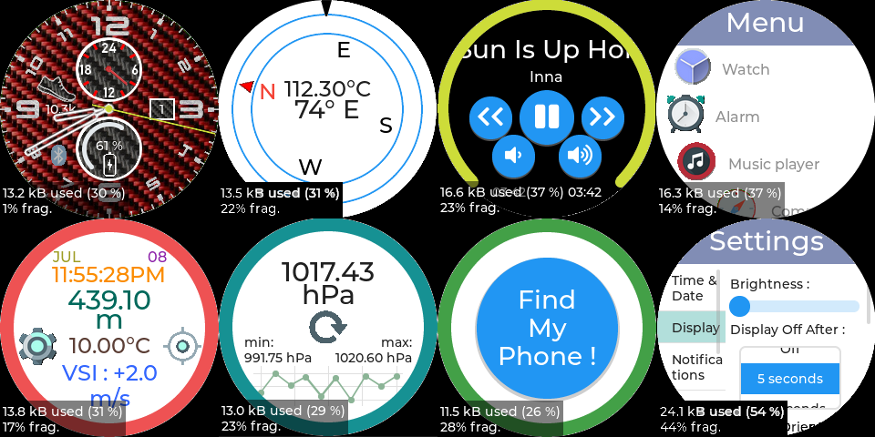
* Three screens designed and working with LVGL :
|
|
* 1 watch face based on a casio watch.
|
|
* 1 menu list screen with icons.
|
|
* 1 setting screen with basic settings (date and time + display brightness) (work in progress).
|
|
* Debug UART on PB_2 (output only)
|
|
* Wake up interrupts handling :
|
|
* Wrist tilt MCU wake up working
|
|
* LCD touch wake up
|
|
* Sensors/Actuators :
|
|
* QMC5883L driver working
|
|
* BMA456 driver working
|
|
* BMP280 driver working (temperature + pressure)
|
|
* Battery voltage sense using ADC is working
|
|
* Vibration motor controlled by PWM working
|
|
|
|
## To do :
|
|
* Write I2C drivers for the :
|
|
* [X] BMA456
|
|
* [X] Wrist tilt detection
|
|
* [X] BMP280
|
|
* [X] Temperature
|
|
* [X] Pressure
|
|
* [X] QMC5883L
|
|
* [X] Write the init sequence for the GC9A01 LCD driver.
|
|
* [X] Make LCD display + touch work.
|
|
* [X] Design and test battery voltage sensing circuit -> voltage divider bridge because ADC input can sense 2.5V Max.
|
|
* [ ] Finish to design the settings page.
|
|
* [ ] Implement a good algorithm to handle adaptiv MCU clock to save power
|
|
* [X] Test the charge circuit.
|
|
* [X] Handle watch auto sleep feature with wake up on screen touch + wrist tilt (POC could be improved).
|
|
* Design and test the :
|
|
* [X] vibration motor circuit
|
|
* [X] Draw the schematic, the first revision of the schematic is available [here](design/Kicad/W800_Smart_Watch/W800_Smart_Watch.pdf).
|
|
* [X] Design the PCB (routing, placement etc..) on a 2 layer PCB - done.
|
|
* [ ] Update the W800 SDK from version 1.00.08 to version 1.00.10 released in January of 2023.
|
|
|
|
## Achieved power consumption recap:
|
|
(Need to work on sleep current :-( )
|
|
| Mode | Current draw | Estimated battery life (450 mAh lipo) |
|
|
|--------------------------|--------------|---------------------------------------|
|
|
|Active (40Mhz clk)<br>(No BLE / No WiFi) |~52 mA | ~8 hour |
|
|
|Active (240Mhz clk)<br>(No BLE / No WiFi) |~72 mA | ~6 hour |
|
|
|Sleep |~4.5 mA |~4 days and 4 hours |
|
|
|Standby |~1.8 mA |~10 days and 15 hours |
|
|
|
|
## Some screenshots of the achieved visuals currently running on the watch using lvgl :
|
|
|
|
|
|
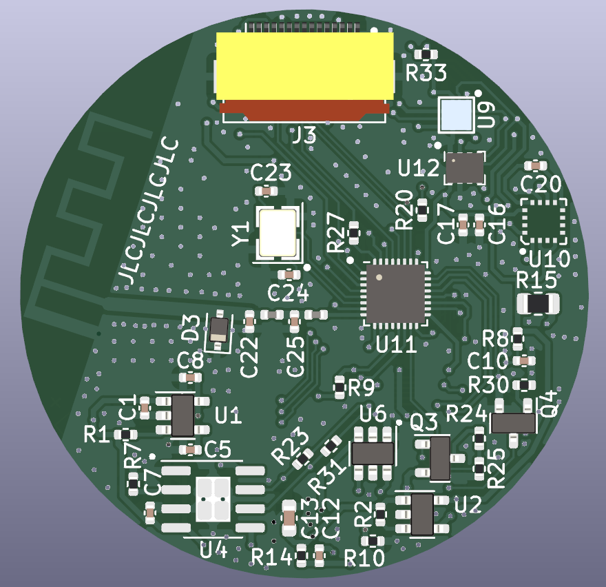
## Here is a preview of what the PCB should look like :
|
|
### The front :
|
|
|
|
|
|
### The back :
|
|

|