|
|
||
|---|---|---|
| schematic | ||
| src | ||
| .gitignore | ||
| LICENSE.md | ||
| README.md | ||
ATMEGA328PU_lowPower_weather_station
What is it ?
An ATMEGA328PU and NRF24L01+ based weather station operating on a single 18650 li-ion battery (or equivalent) and a solar panel.
On this page is displayed the data collected by this very unit !
Check the LICENSE.md file at the root of this project for more information.
What are the functionalities ?
The station is equipped with the following sensors and functionalities :
- Temperature (BMP280 and HTU21)
- Humidity (HTU21)
- Compensated humidity (HTU21)
- Pressure (BMP280)
- Sunlight (LDR)
- Battery level indication (ATMEGA's 10 bit ADC)
Power consumption :
- Around 60µA during sleep.
- Around a 13mA spike during data transmission and 4mA during sensor data collection.
- The solar panel is enough to even charge the battery, it should thus never need to be replaced or recharged externally.
Project folder architecture :
/
|_src                   This folder contains all the C/C++ file sources.
| \_app                 This folder contains the main app and it's dependencies.
| |_libs                This folder contains all the required 3rd party libraries that should be put in "Arduino\libraries" folder in order for the app to compile.
| |_test                This folder contains a test program which was used to test the dependencies.
|
|_schematic             This folder contains all the files associated with the schematic.
| \_KiCad               This folder contains the KiCad files associated with the project.
| |_ATMEGA328PU_lowPower_weather_station.pdf    Which is the most recent schematic exported as a pdf for quick viewing.
|
|_documentation         This folder may one day contain the associated documentation if needed.
|
|_.gitignore
|_LICENSE.md
|_README.md             The content of this page
Getting started :
- Clone this repository : git clone http://web-directories.cf/git/Th3maz1ng/ATMEGA328PU_lowPower_weather_station.git
- Go to "src\libs" folder of this project and copy and paste its content in your "Arduino\libraries" folder.
- Open the app.ino file with the Arduino IDE and select the "Arduino Pro or Pro Mini" board with processor : (Atmega 3.3V 8 Mhz).
- Compile and Upload !
- To receive the data sent by the station, you can check this other project which is the receiver end.
Configuration options :
You may change some settings present in the definition.h file.
Set SLEEP_4_SEC_INTERVAL which corresponds to the time interval between each data transmission in 4 seconds increments. 1 minute by default corresponds to a value of 15.
Set SERIAL_DEBUG_ENABLED to 1 to get debug output on the serial console.
Set SERIAL_BAUD_RATE to the desired baudrate for debugging.
Set ADC_QUANTUM to adjust the quantum if your VREF is not the same as mine.
To do so, measure which voltage does the VCC pin of your Arduino board output and divide it by 1024 (10 bit ADC resolution).
Set VOLTAGE_DIV_COEFF to something different if you changed the voltage divider resistor values.
Set RADIO_CHANNEL to the NRF's RF channel (between 0 and 125). Do not forget to set the receiver station up on the same channel
Set RADIO_NODE_ADDRESS to change it's 5 byte address if you feel like it. Do not forget to set the receiver station up on the same address
Set RADIO_PA_LEVEL to adjust the transmit power level if needed (higher the power, higher the current consumption)
Set ENABLE_LNA to true or false to enable or disable the Low Noise Amplifier on the NRF modules if it has one.
The hardware :
Here is a list of the parts used to build the station with a link to where you can buy them :
- Solar panel : 72x72
- NRF24L01+
- TC4056 (1 cell lipo charge/discharge protection)
- BMP280 pressure sensor
- SHT/HTU 21 humidity sensor
- ATMEGA328PU board
- 3.3V LDO for the power rail : RT9013-33PB
- LDR type : 5528
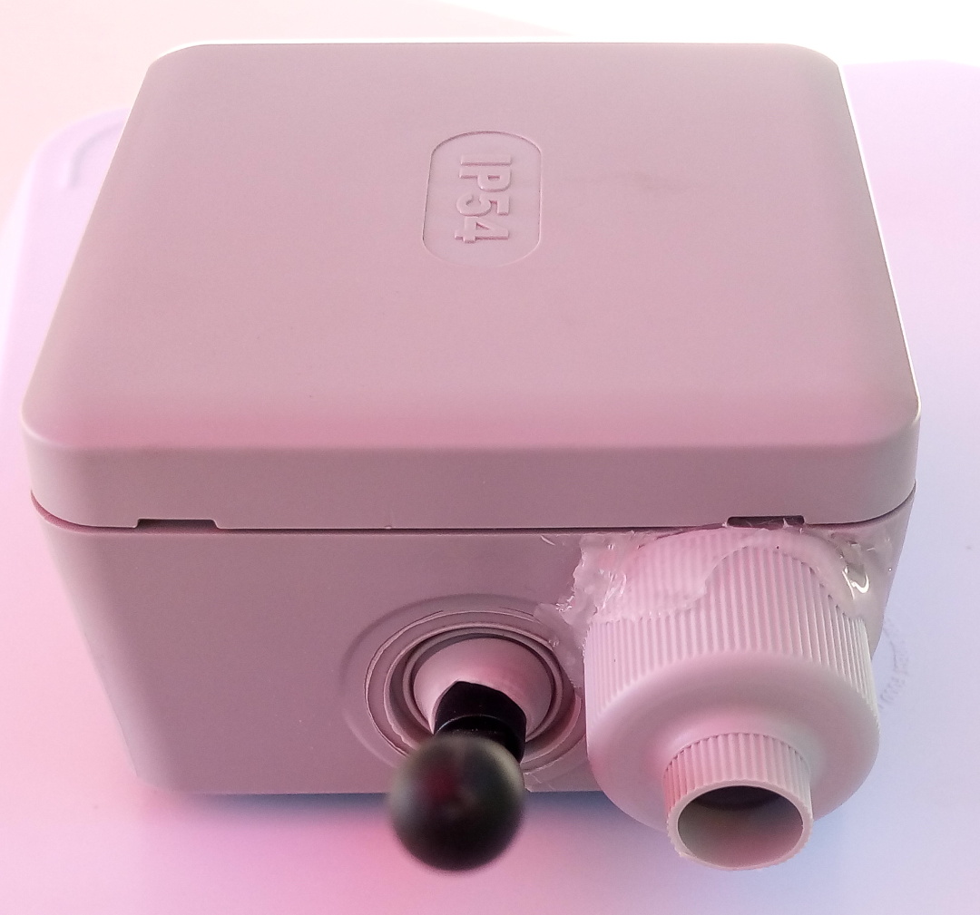
- Small junction box
If you have any questions, do not hesitate to contact me at : bugreport[at]laposte[dot]net
Finally here are some pictures of the PCB and device :
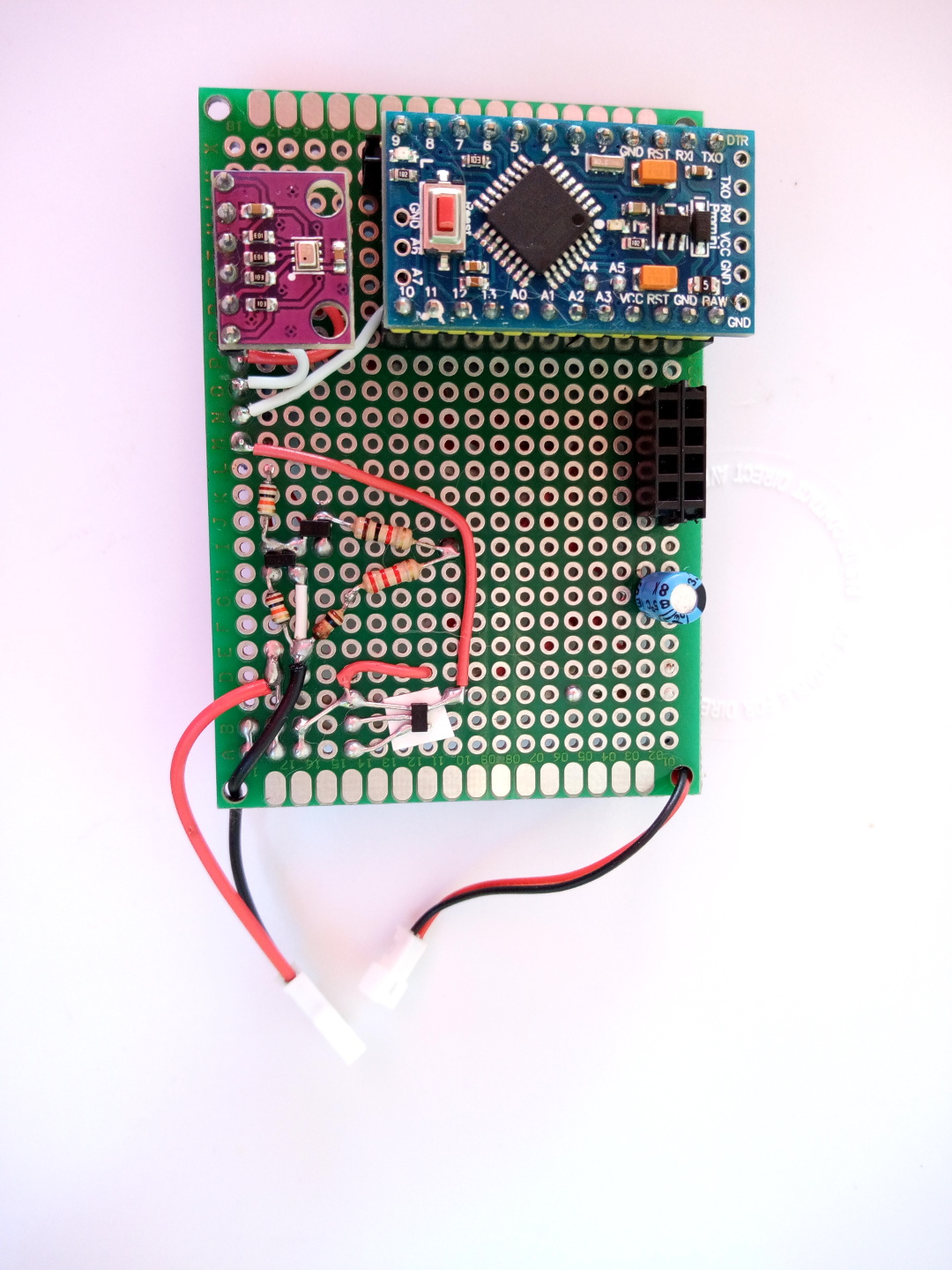
PCB top view :
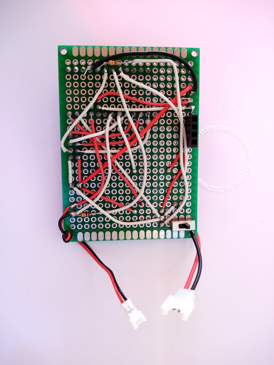
PCB back view :
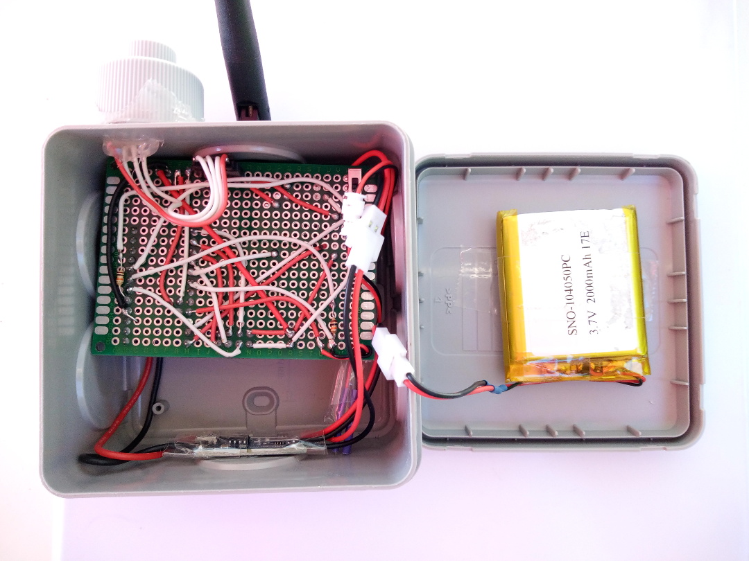
Device's internals :
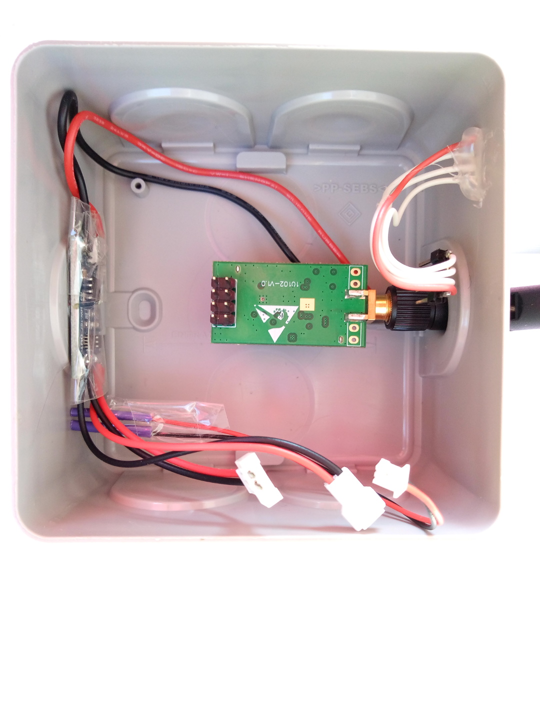
Device's internals with the PCB removed :
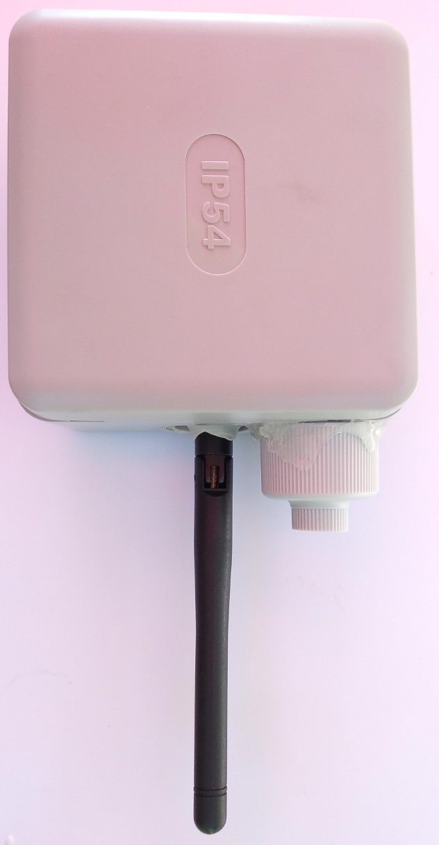
Device form factor :
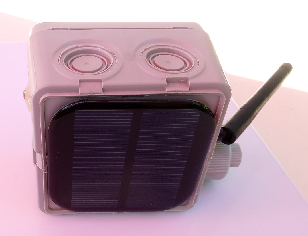
Device's LDR and solar panel :
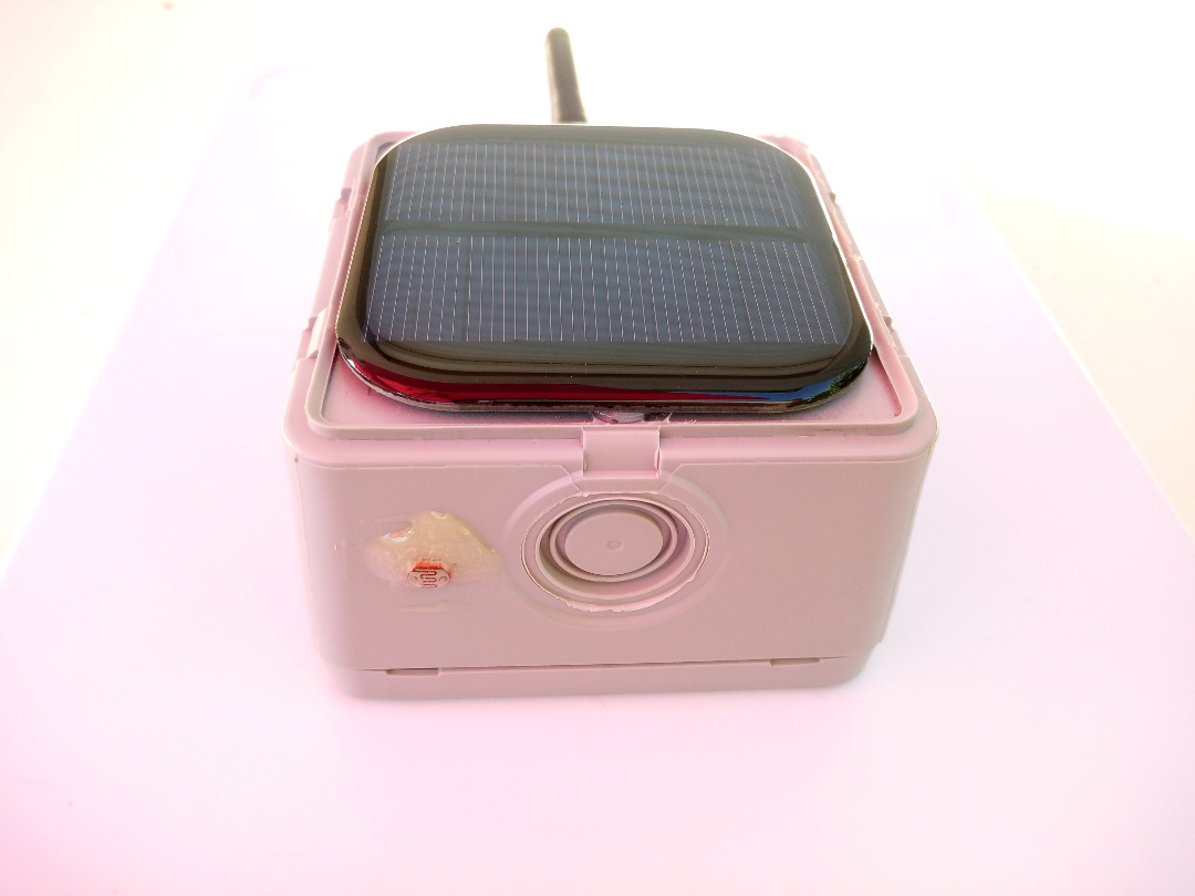
Device's antenna and SHT/HTU 21 cover :