| schematic | ||
| src/app | ||
| .gitignore | ||
| LICENSE.md | ||
| README.md | ||
ATMEGA328P_connectedMailBox
What is it ?
This system is an ATMEGA328P and NRF24L01+ based low power device to detect when something is posted in my mail box. The electronic circuit shares the same designed as the low power weather station I made enabling it to consume only 60µA when sleeping.
You will also need to build a receiver station to receive the messages. For that you can build your own or use this design I made.
Check the LICENSE.md file at the root of this project for more information.

What is this device capable of ?
The system is able to wait for up to three distinct events (interrupt sources). This means that it can detect up to three actions like :
- A letter was delivered in the mail box using the small letter tray.
- A package was delivered using the door.
- The mail was picked up using the rear door by me or a family member.
Changing the design of the event detection circuit can easily increase the number of various events that could be detected
The schematic is available here.
The device is fixed to the mailbox using two strong neodymium magnets. No need to make holes in the box.
Power consumption :
- The device consumes around 60µA when sleeping (ie : waiting for an event to happen).
- The device consumes around 13mA for a very short period of time when transmitting a RF packet after an event was detected.
- The current design is using a 2000mAh LiPo battery which should last for at least four years of every day use. /!\ I may update the design to add a solar pannel like I did for the weather station.
Project folder architecture :
/
|_src               This folder contains all the C/C++ file sources.
| \_app             This folder contains the main app and it's dependencies.
|  |_libs           This folder contains all the required 3rd party libraries that should be put in "Arduino\libraries" folder in order for the app to compile.
|
|_schematic         This folder contains all the files associated with the schematic.
| \_KiCad           This folder contains the KiCad files associated with the project.
| |_ATMEGA328P_connectedMailBox.pdf             The most recent schematic exported in pdf format for quick viewing.
|
|_documentation     This folder may one day contain the associated documentation if needed.
|
|_.gitignore
|_LICENSE.md
|_README.md             The content of this very page
The hardware needed to build the system :
Here is a list of the parts I used to build my connected mailbox system.
You will find a link next to the parts name. I do not have any partner ships with the sites in the links.
- 1 * Shielded NRF24L01+
- 1 * TC4056 (1 cell lipo charge/discharge protection)
- ATMEGA328PU board (3.3V 8Mhz version)
- 1 * 3.3V LDO for the power rail : RT9013-33PB
- Small junction box 8cm * 8cm * 5cm
- 2 or 3 x reed switches with 3 poles
- 1 * sliding ON/OFF switch
- 4 * Plugs (male and female) : 1 for the battery + 3 for the reed switchies
- 1 * 18650 LiPo cell
- 1 * 18650 LiPo holder
- 2 * Neodymium magnets
- 1 * IRLML6402 P-channel MOSFET
- 1 * IRLML2502 N-channel MOSFET
- 3 * 10K resistor
- 1 * 1K resistor
- 1 * 3.9K resistor
- 1 * 3.2K resistor
- 1 * 5K resistor
- 1 * 15K resistor
- 1 * 20K resistor
- 1 * 8.2K resistor
Getting started :
- Clone this repository : git clone http://web-directories.cf/git/Th3maz1ng/ATMEGA328P_connectedMailBox.git
- Go to "src\libs" folder of this project and copy and paste its content in your "Arduino\libraries" folder.
- Open the app.ino file with the Arduino IDE and select the "Arduino Pro or Pro Mini" board with processor : (Atmega 3.3V 8Mhz).
- Compile and Upload !
- To receive the data sent by the device, you can check this other project which is the receiver end.
Configuration options :
You may change some settings present in the definition.h file located in the "src/app" folder.
If you have any questions, do not hesitate to contact me at : bugreport[at]laposte[dot]net
Finally here are some pictures of the PCB, reed switches setup and mailbox :
Overall device:

Junction box layout closeup:

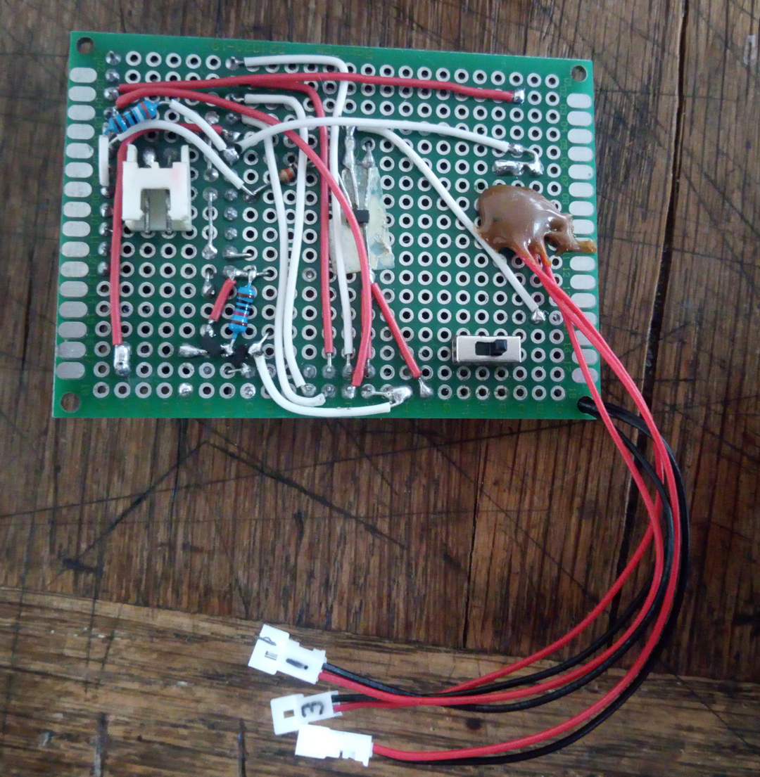
PCB back :

PCB front :
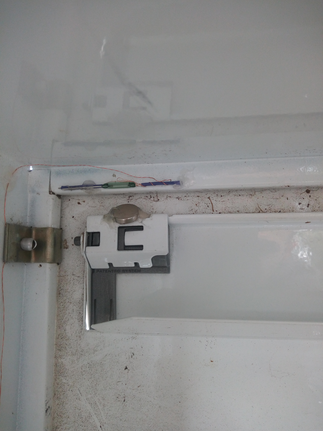
Reed switch installation in the mailbox :

Package door lock reed switch closeup:

Letter tray reed switch closeup: